Overview
In this project, I implemented a triangular mesh editor. Triangular meshes are especially useful in modeling 3D objects, and are implemented by using a set of vertices, edges, and faces to represent an object’s surface.
To create the mesh, I used Bézier curves to create Bézier surfaces using de Casteljau’s algorithm. Bézier curves and surfaces take in a series of control points, and use the points to generate a smooth output that approximates their positions. Then, I implemented area-weighted vertex normals to shade the mesh based on the Phong shading model, which is better suited to smooth surfaces than a flat shading model. Finally, in order to utilize meshes flexibly, I implemented functions that allowed for mesh manipulation and greater customization: edge flip, edge split, and loop subdivision for mesh upsampling.
Section I: Bézier Curves and Surfaces
Part 1: Bézier curves with 1D de Casteljau subdivision
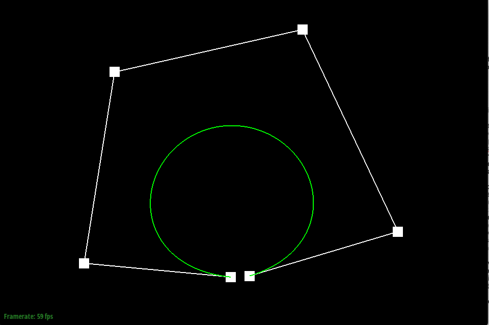
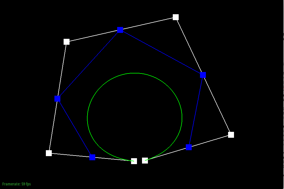
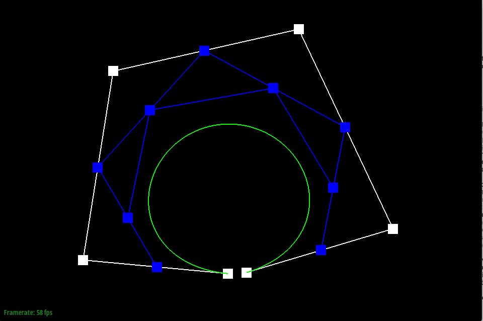
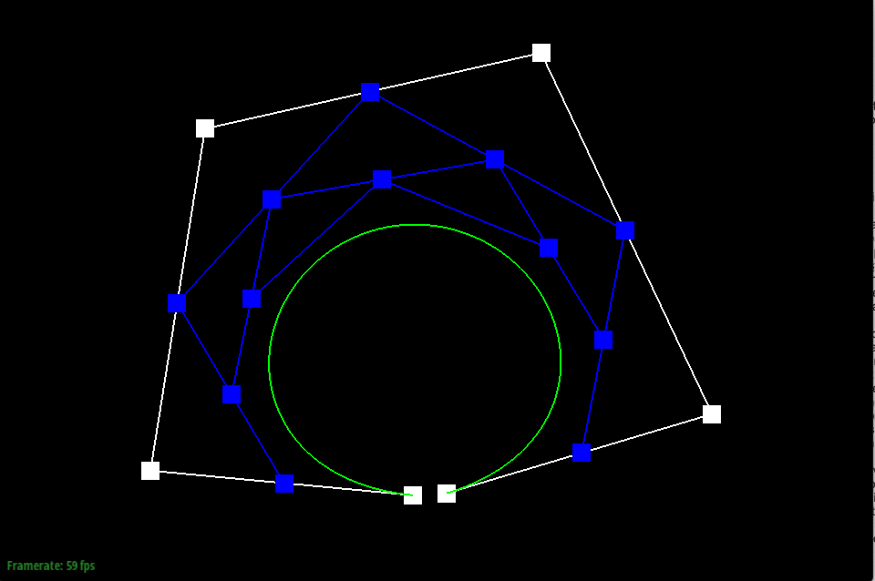
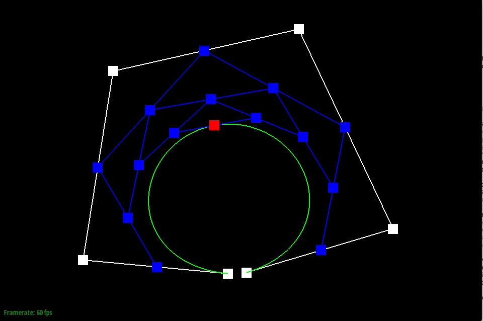
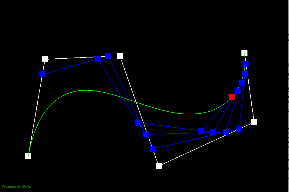
De Casteljau’s algorithm is used to create a Bézier curve using a series of control points. To do this, de Casteljau treats the line created between each consecutive control point as a parameterized line, and finds the location of a point at time t on each line. If you started with n control points, one step of de Casteljau will yield n-1 new points. Then, the algorithm is continued, where new lines are created between the new points, and another set of points is found on the new lines. De Casteljau is continued until there is just one point yielded, which is used to trace and model the Bézier curve at time t.
In my implementation of de Casteljau’s algorithm, I used the function evaluateStep to yield the new points found at each step of the algorithm. evaluateStep takes in points as an argument and yields points on return, allowing it to be continuously called on a set of control points until just one point is left to model the Bézier curve. First, I found the number of points given by calling size on the vector points, the argument given. As a base case, if there is only one point, the de Casteljau algorithm is complete and only that point is returned. If there is more than one point given, the function creates a parameterized line between each consecutive point stored in the vector and evaluates the line at the given time t to yield a new point. To execute this, I used a for loop that iterated from index 0 to the number of points - 1 in the points vector given, since each line is drawn between two points, to set the new points in the new vector nextcp, which is returned at the end.
|
|
|
|

|
|
Part 2: Bézier surfaces with separable 1D de Casteljau subdivision
While a Bézier curve is modeled using control points in space, a Bézier surface is modeled using points on a series of Bézier curves, created from control points in a 3D space. In other words, when given an n x m grid of control points, each row of m control points are used to create a Bézier curve. Then, with the n Bézier curves made from de Casteljau’s algorithm, n points are evaluated at the same parameter u on the curves, and used as control points to evaluate a new Bézier curve at parameter v. Together, the parameters u and v model a smooth surface.
To create Bézier surfaces, I implemented the evaluate function in BezierPatch, a function that takes in the parameters u and v, and outputs a 3D Vector of points. First, I found the number of rows in the control points vector given by taking its size. Then, I iterated through each row and evaluated the points in each row at time u, using the de Casteljau algorithm, and stored them in a vector upts. Finally, I evaluated the vector upts using the de Casteljau algorithm at time v.
Section II: Triangle Meshes and Half-Edge Data Structure
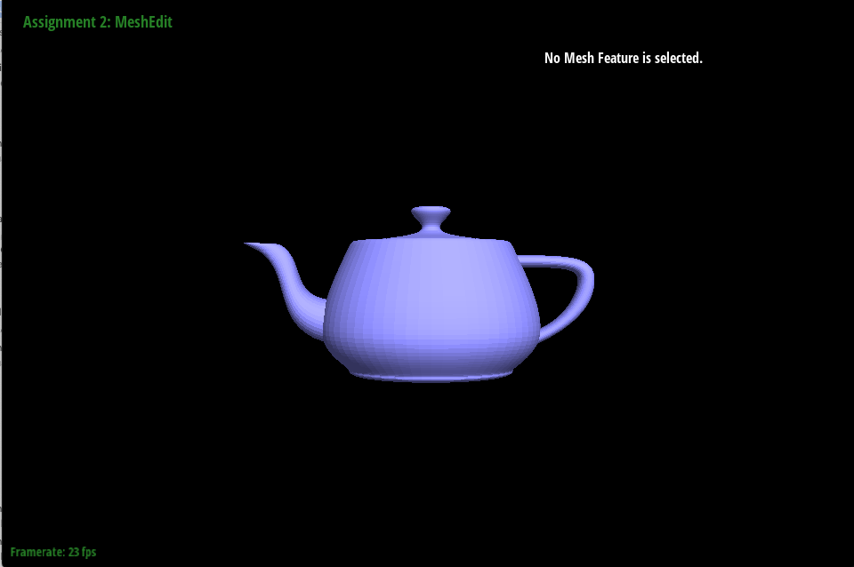
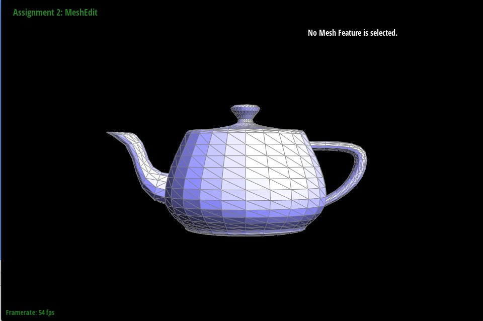
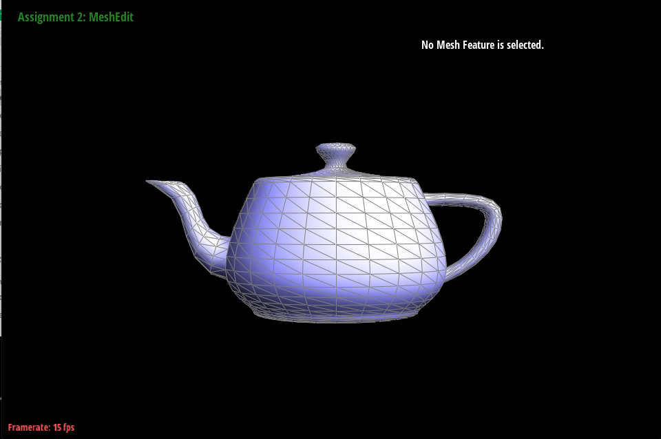
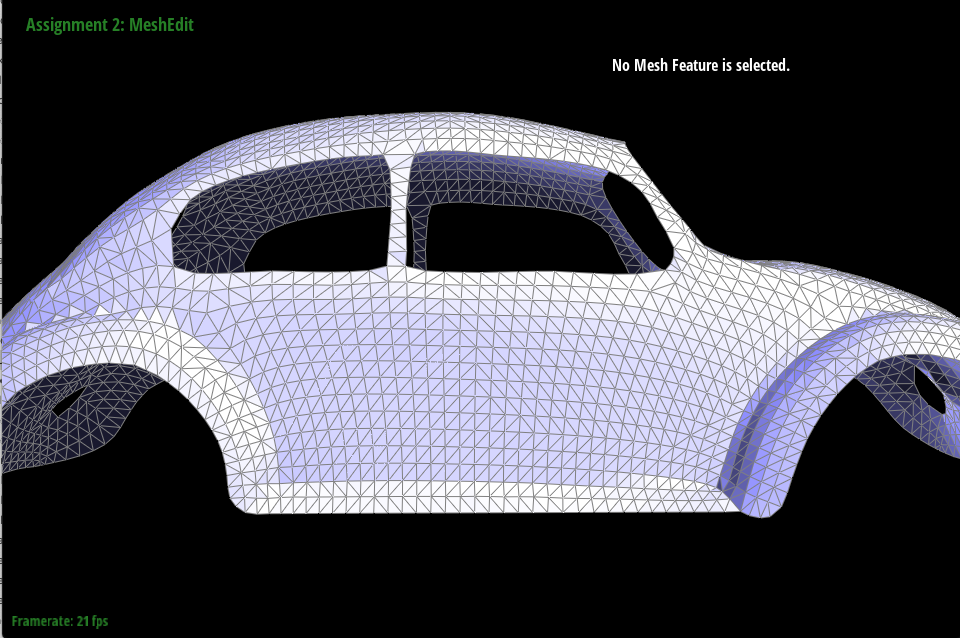
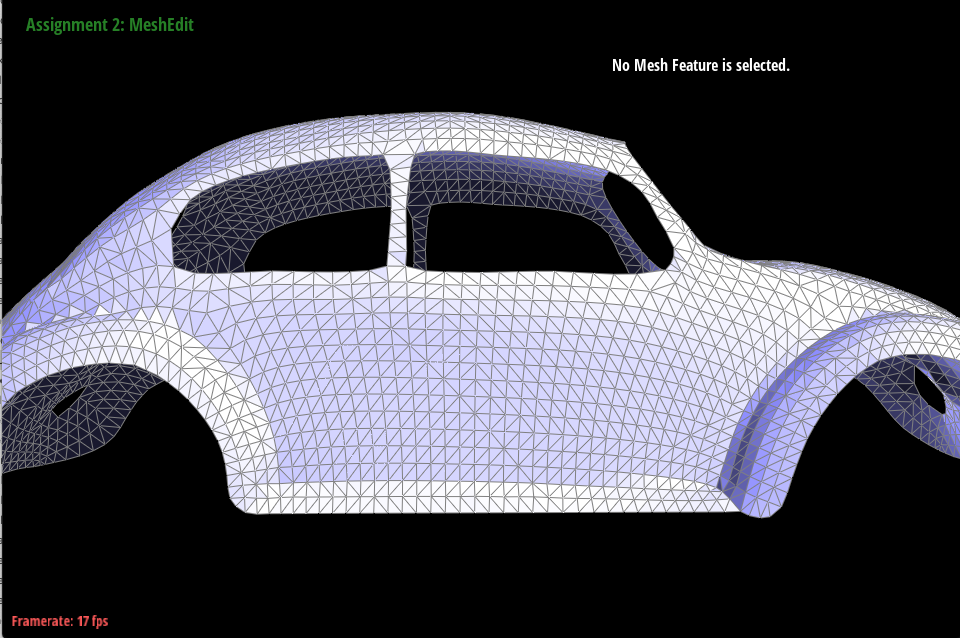
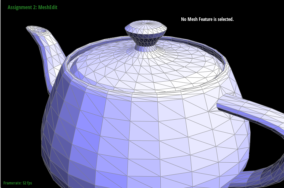
Part 3: Average normals for half-edge meshes
In the mesh implementation, surfaces are modeled using edges, vertices, faces, and halfedges. Halfedges are data structures used for easy mesh traversal, and are what link edges, vertices, and faces together. To implement the area-weighted vertex normal for a vertex v, I first accessed the twin of the halfedge of the vertex and stored it as h. Every edge has two halfedges that are ‘twins’ of each other. I used h to iterate through all the neighboring vertices and faces of v. For each face, I labelled the two vertices opposite our original vertex v as ptb and ptc. I used their positions to calculate the area of the face, by taking the cross product of their distances to v and dividing by 2. Then, I multiplied each face’s area with their normal vector, and summed the vectors in a vector value declared outside of the loop, called normal. Once all vertices had been iterated through, I normalized the vector normal and returned it.
|
|
Part 4: Half-edge flip
When implementing an edge flip, I had to be very deliberate in reassigning pointers of the vertices, edges, faces, and halfedges affected. Not only did I have to keep track of pointers to new places, but I also had to be sure that other pointers were not modified incorrectly and continued to point to the right places. I drew a large table to keep track of the pointers for all of the structures used. In flipEdge, there are two faces, abc and bcd, made up of four vertices a, b, c, and d. There are five edges, ac, ab, bc, and bd, of which bc, the divider of the two faces, flips to connect vertices a and d instead. I accessed all of these elements through the given edge, e0, which I returned at the end. If the edge was on the boundary, I simply returned it. If not, I accessed all elements and set their pointers accordingly.

|

|
|
|
Part 5: Half-edge split
To implement a split edge, I followed the same method I used for flipEdge, where I drew out all the elements that needed to be modified, and in this case, added. While in flipEdge there were no new elements, only reassigned pointers, in splitEdge three new edges were created. The three new edges required two new faces, and six new halfedges. It also required a new vertex, m which is initialized to the midpoint of the edge passed in as an argument to splitEdge. Like in flipEdge, I accessed all elements through the passed in edge e0, and returned without implementing the splitEdge if e0 was on the boundary. If e0 was on the boundary, I returned a vertex of its halfedge. Else, I updated all elements accordingly and returned vertex m.

|

|
|

|
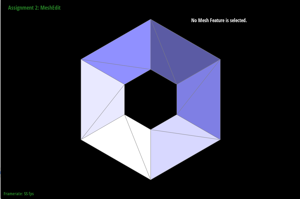
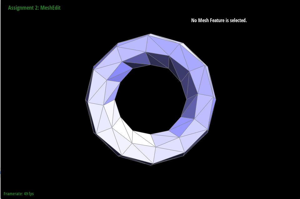
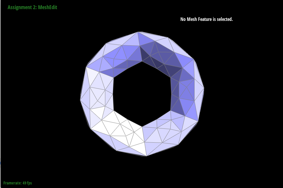
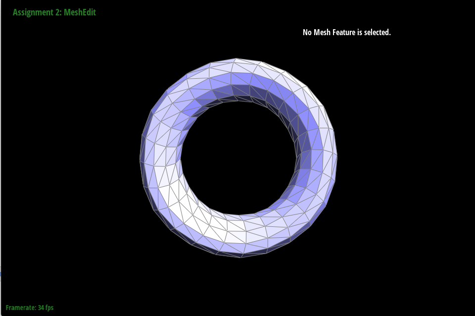
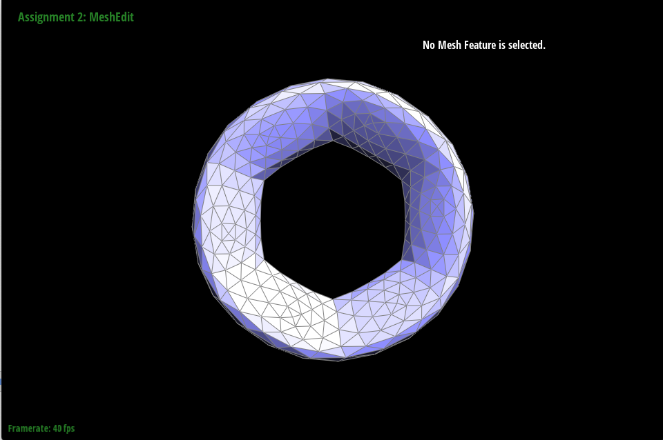
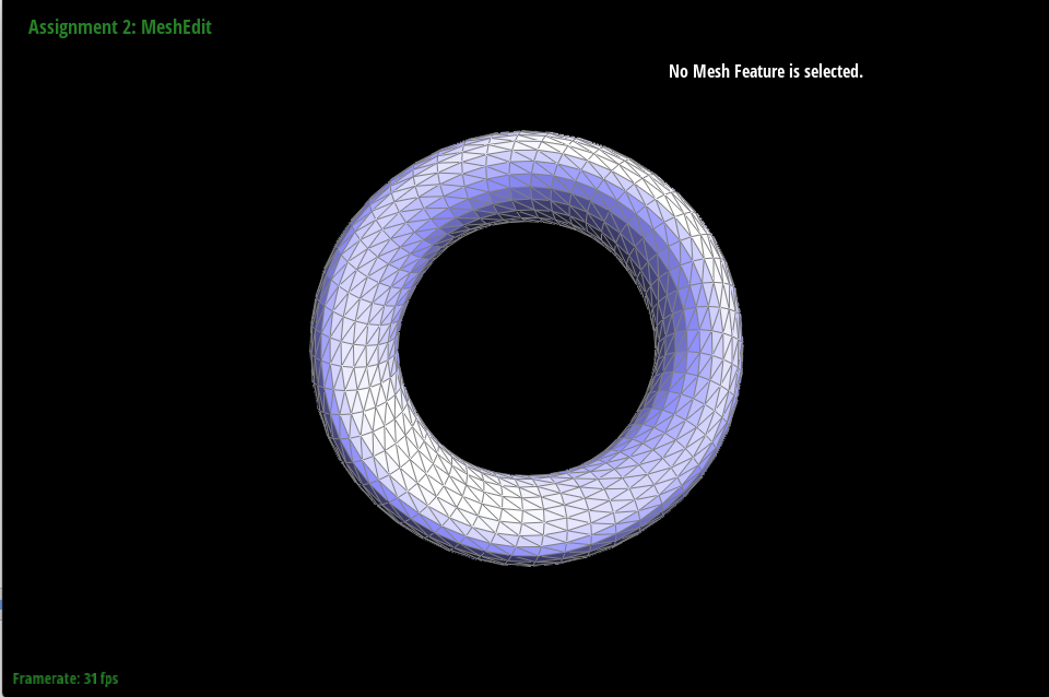
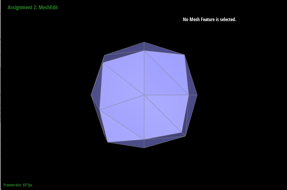
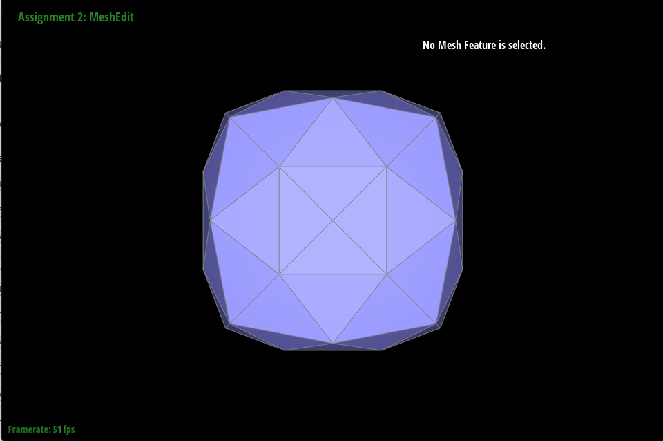
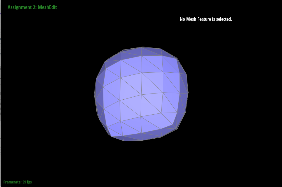
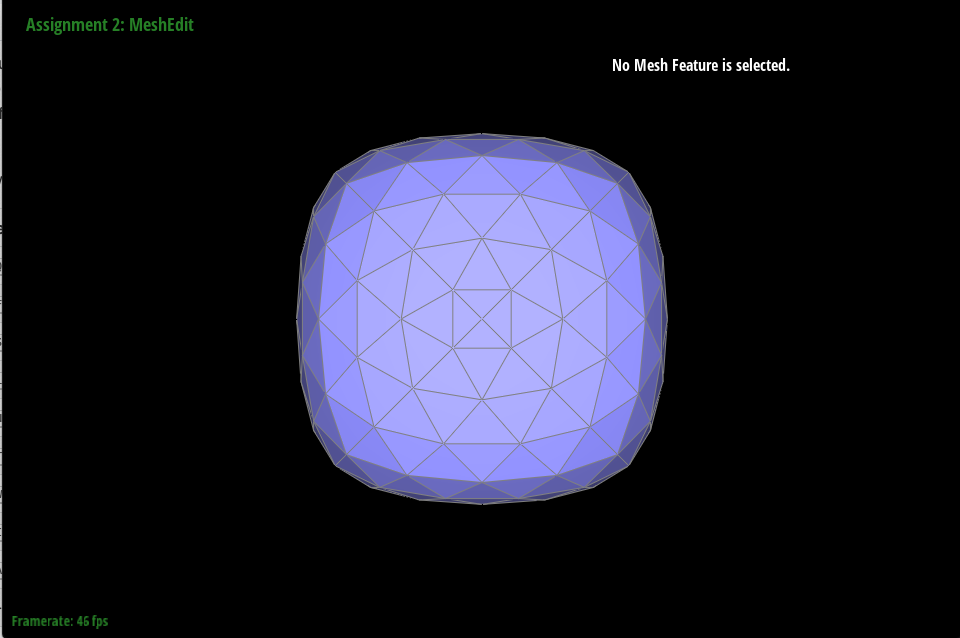
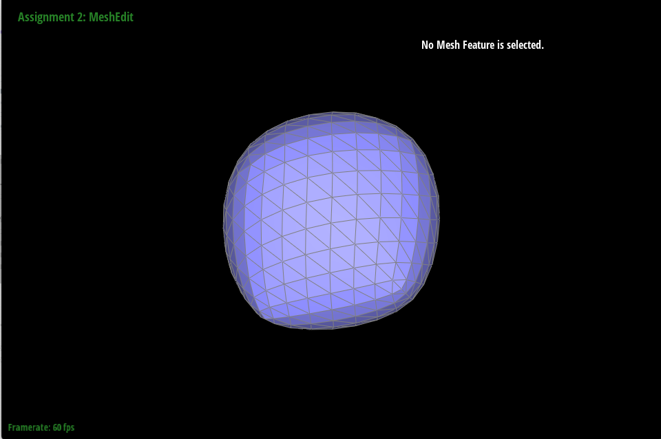
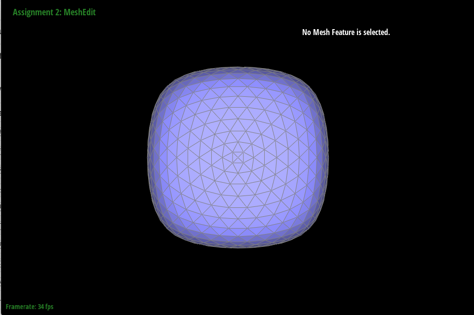
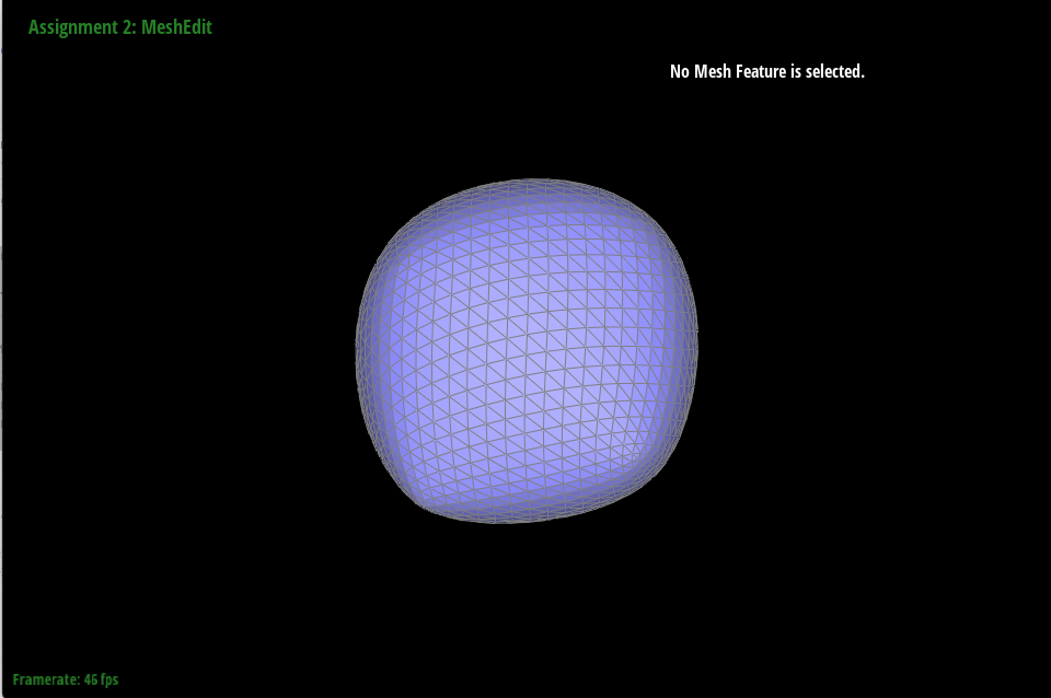
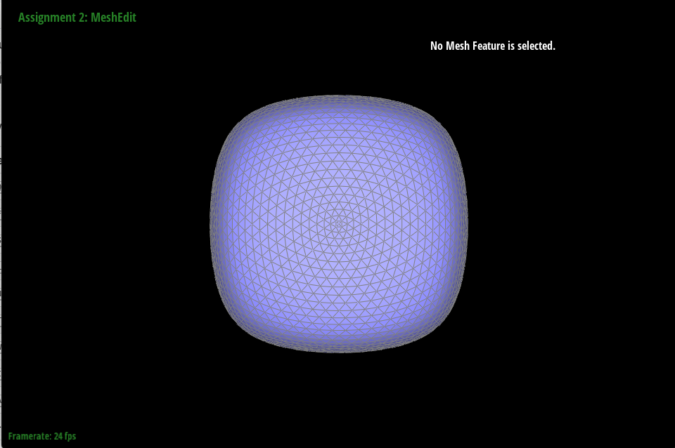
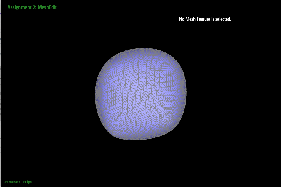
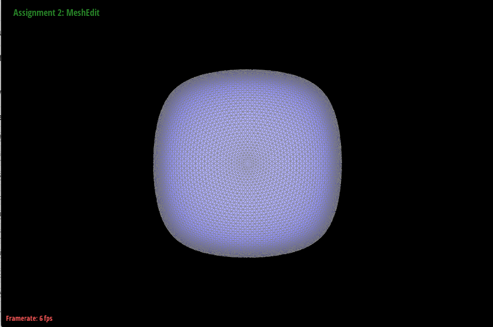
Part 6: Loop subdivision for mesh upsampling
In upsample, a function that takes in an entire mesh and upsamples it using loop subdivision, I implemented five parts. Upsampling the mesh requires moving vertices from their original positions so that the mesh’s shape is retained, but I did not want to manipulate the positions of the vertices while I was still traversing it. First, I iterated through all the edges of the mesh and updated the newPosition variable of each edge and set their isNew variable to false. Then, I iterated through all the vertices of the mesh and calculated their new position based on the degree of the vertex and the sum of the positions of its neighbors, and stored their new position in their newPosition variables. I also updated their isNew variable to new. In the third part, I iterated through the edges of the mesh again and split each one, updating the position of the returned vertex m to be the position stored in each edge’s newPosition variable. I updated the splitEdge function to change the isNew variable of all new elements to true. In the fourth part, I iterated through the edges again, and flipped the edge if it was both a new edge and if it connected an old vertex with a new one. Finally, I iterated through all the vertices of the mesh and updated their positions to their newPosition variables.
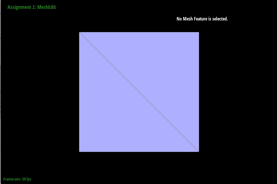
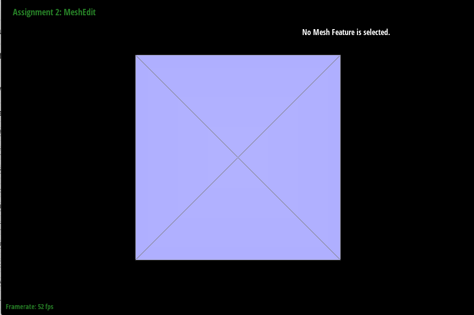
After loop subdivision, sharp corners and edges became rounded. To reduce this effect, I pre split some edges, specifically the ones between two faces that faced the same direction.
|

|
|
|
|
|
|

|
Further, we can use edge splits and flips to reduce the asymmetry that occurs when upsampling a cube.
|
|
|
|
|
|
|
|
|
|
|
|